

Short answer
- Straight probe for general use, 0 to 1500 µm, in ferrous, non-ferrous or combined versions.
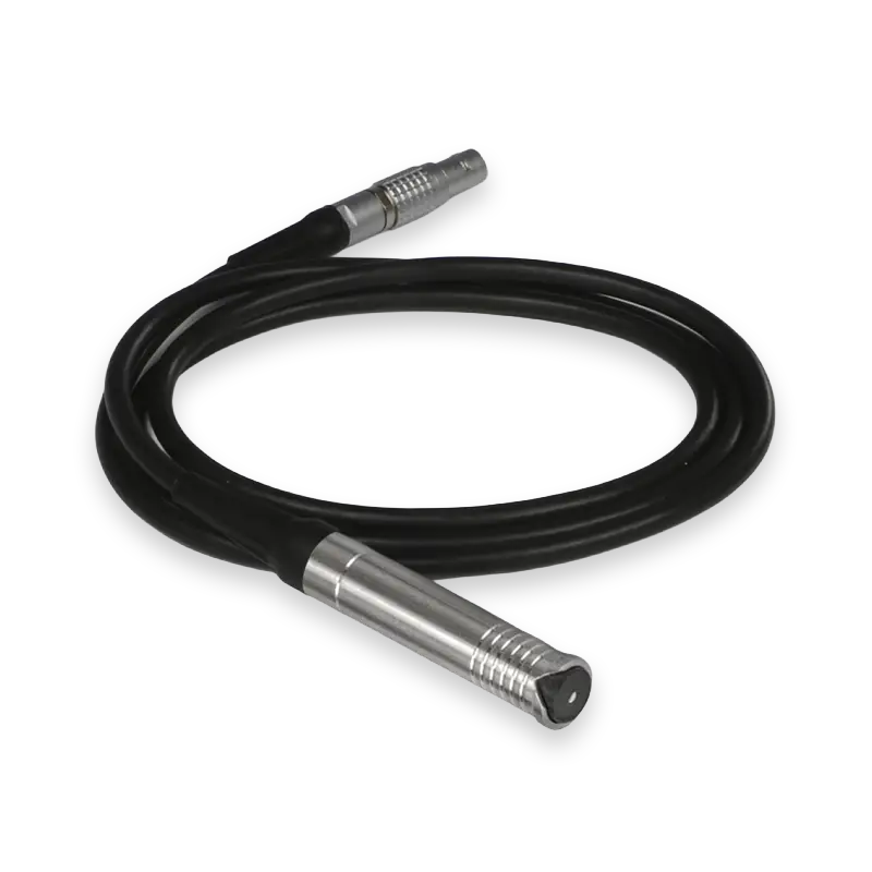
- V-cut probe for pipes, round sections and cylindrical parts.
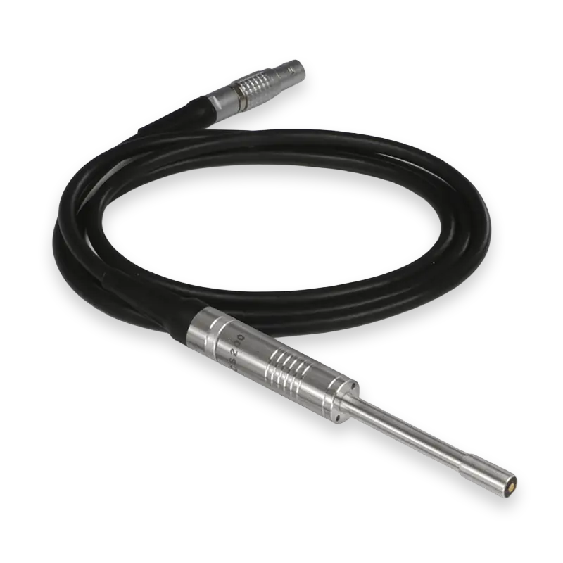
- Miniature probe for edges, corners, interiors and tight spaces (ferrous substrate).
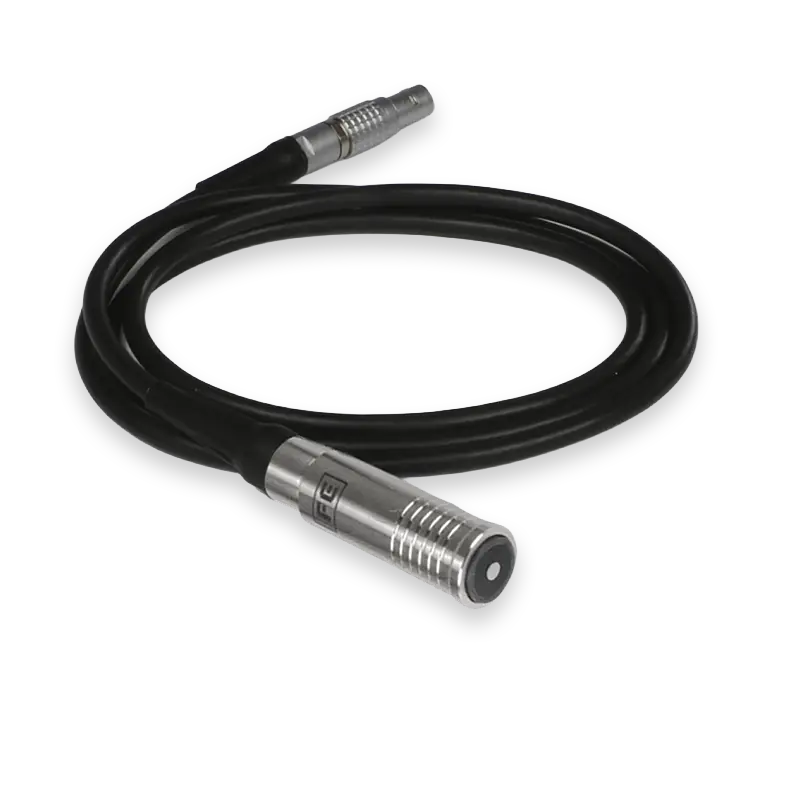
- Extended-range probe for thick coatings, up to 5000 µm (ferrous substrate).
- Each probe is calibrated on its matching base, with foils of known thickness.
With its combined probe, the QC5 DLC recognises on its own whether the substrate is ferrous or non-ferrous and measures both with no change of probe or setting.
Problem 1: the reading jumps on pipes and round parts
The symptom: on a pipe or shaft, the probe rocks and every reading comes out different.
Why it happens: the tip of a straight probe rests on a single point of the curve and any tilt changes the distance to the substrate.
How it is solved: with the V-cut probe, which sits on the curve and stays perpendicular. Available in ferrous, non-ferrous and combined versions.
Problem 2: edges, corners and tight spaces
The symptom: the standard probe doesn't fit inside a part, into a groove or next to an edge.
How it is solved: with the miniature probe, with a reduced tip, in straight, 45° or 90° versions, and extra-long made to order in segments to reach interiors. Ferrous substrate only.
Next to an edge, any magnetic probe reads less reliably, because the substrate "runs out" under the tip. A small probe reduces that effect but doesn't remove it: don't calibrate near edges.
Problem 3: the coating is thicker than the probe's range
The symptom: on thick linings, the reading goes out of range or loses accuracy.
How it is solved: with the extended-range probe, which measures 0 to 5000 µm on ferrous substrates. It is calibrated on its own 75 × 75 mm base.
Problem 4: steel and aluminium parts in the same job
The symptom: you have to change probe or setting every time the substrate material changes.
Why it happens: on steel, measurement is by magnetic induction, and on aluminium, copper or non-magnetic stainless steel, by eddy currents: two different principles.
How it is solved: with a combined probe, which recognises the substrate type and measures on both. With the QC5 DLC, detection is automatic.
Problem 5: measuring with a poorly calibrated probe
The symptom: readings are stable, but don't match the real thickness.
How it is solved: by calibrating each probe on a base of the same type as the part (carbon steel for ferrous, aluminium for non-ferrous) and with foils of known thickness. For best accuracy, use two foils, one below and one above the thickness you expect to measure, at least 100 µm apart. The kits include a base and a set of three foils (low, medium and high).

If the real substrate is blast-cleaned, calibration must account for roughness: see the guide on paint thickness to ISO 19840.
Which probe to use, case by case
| Your part | Probe | Substrate |
|---|---|---|
| Flat or slightly curved, general use | Straight, 0–1500 µm | Ferrous, non-ferrous or combined |
| Pipes, shafts, round sections | V-cut | Ferrous, non-ferrous or combined |
| Edges, corners, interiors, grooves | Miniature (straight, 45°, 90°, extra-long) | Ferrous |
| Thick coatings, up to 5000 µm | Extended range | Ferrous |
| Steel and non-ferrous in the same job | Combined (automatic with the QC5 DLC) | Ferrous and non-ferrous |
Standard and special probes are compatible with the QC5 and QC3. Source: DEMEQ, QC5 manual and QC probe and accessory range.